Railroadforums.com is a free online
Railroad Discussion Forum and
Railroad Photo Gallery for railroaders, railfans, model railroaders and anyone else who is interested in railroads. We cover a wide variety of topics, including freight trains, passenger and commuter railroads, rail news and information, tourist railroads, railway museums and railroad history.
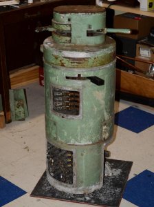
On an old style EMD control stand that has a transition/braking lever. What were the position indicators that showed in the tiny square hole that faced the engineer? On the throttle it was idle 1,2,3,4,5,6,7,8. These had lights behind them. It looks like there are 4 transition positions with detents and then about 45 degrees of no detents for the dynamic braking. Pictures soon.
Tom, I can't tell you in so many words the different positions of the transition lever; however, if you would care to look up any of the older EMD locomotive operator's manuals ( especially any of the F units ) you will find the answer to your question. The operator's manuals may be found on the Fallen Flags website (
http://www.rr-fallenflags.org/ ). Scroll down the front page until you find the title " Operator Manuals ". Hope this will help you.
Extremely helpful. I have a F3 operators manual for a C&NW locomotive but it does not have some of the instructions for the manual transition lever. I went thru about 6 operators manual and the electrical diagrams and found the position designations. The original issue I was having is that the legend plate that shows through the window is missing on my control stand and I need to make a new one. The info I found will help me make that indicator. In case anybody needs to know.....from left to right .........4,3,2,1,off,B. There is question of what shows thru from off to B, but I may have to go to a museum for that. Thank You. Tom
Extremely helpful. I have a F3 operators manual for a C&NW locomotive but it does not have some of the instructions for the manual transition lever. I went thru about 6 operators manual and the electrical diagrams and found the position designations. The original issue I was having is that the legend plate that shows through the window is missing on my control stand and I need to make a new one. The info I found will help me make that indicator. In case anybody needs to know.....from left to right .........4,3,2,1,off,B. There is question of what shows thru from off to B, but I may have to go to a museum for that. Thank You. Tom
I think Aaron told me that it was not manual transition. The second lever is only dynamic brakes. Did you get it go into fwd or rev or is it still stuck in neutral?
From what I can divine from all the manuals, there is a blocking plate over the transition part if it has auto transition and a plate over the dynamic section if that option is not installed. Mine has no blocking plates so I could set it up for either. The manuals explain all the interlocks and what positions each lever must be in for another lever to be moved. Everything seems to work correctly. You have to have the transition lever in the off position and the throttle in the off position to get the reverser out. And the transition lever in 1 and throttle in off or idle to move to fwd or rev.
With the advent of the F7, EMD models were equipped with automatic transition control; however, there was still a transition lever on the control stand to supplement those units in the consist that did not have automatic transition ( i.e. F3's and older ). The first dynamic brake control was also factored into the controls at this point. I'm not sure when this particular lever was done away with, but I'd bet it was around the time of the 645 Prime Mover. I remember seeing many SD40 & SD45 control stands with dedicated Dynamic Brake levers. As always, feel free to correct me if I am wrong on this.
As I looked at the transition lever last nite I noticed there is not enough notches for manual transition and there is a blocking plate. If I don't get too OCD about it I will build a legend plate and hook the whole thing to the model railroad and away we go.
Here is what it looks like. Upper left is Dynamic Brake. Center is the reverser. Throttle is upper right. I'll polish the brass parts, scrape off the loose paint and give a Earl Scrieb $99 special and it will ready to wire to the model RR. The covers are off. There is a lot of electrical stuff in there.

So did you get the reverse lever with the control column, or did you have to fabricate one on your own? And where did you find this jewel?
It is a plastic reverser that came with it, however I have drawn it in Autocad and will make a nice aluminum one. I have a brass one somewhere. But I must have put it a box of stuff in the attic cause it is not on it's shelf. If I move it from the first place I put it I usually can't find it. The unit was legally obtained from a locomotive scrapper. Tom
RailroadForums.com is a participant in the Amazon Services LLC Associates Program, an affiliate advertising program designed to provide a means for sites to earn advertising fees by advertising and linking to amazon.com
RailroadBookstore.com - An online railroad bookstore featuring a curated selection of new and used railroad books. Railroad pictorials, railroad history, steam locomotives, passenger trains, modern railroading. Hundreds of titles available, most at discount prices! We also have a video and children's book section.
ModelRailroadBookstore.com - An online model railroad bookstore featuring a curated selection of new and used books. Layout design, track plans, scenery and structure building, wiring, DCC, Tinplate, Toy Trains, Price Guides and more.
|
Affiliate Disclosure: We may receive a commision from some of the links and ads shown on this website
(Learn More Here)


